Sewage disposal
Rotary mechanical grid decontamination machine
use
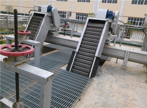
SGH rotary solid-liquid separator (also known as rotary grid decontamination machine) is an advanced solid-liquid separation equipment for water treatment. It is mainly used at water inlets of urban sewage treatment plants, district sewage pretreatment devices, municipal rainwater and sewage pumping stations, waterworks and power plant cooling water. The equipment is also widely used in water treatment projects in various industries such as textile, printing and dyeing, food, aquatic products, paper making, slaughtering, leather making, etc. It is an ideal solid-liquid separation equipment in water treatment industry.
Structure and working principle
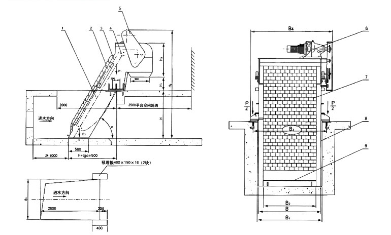
The device adopts a rotary type, and plough-shaped rake teeth with a special shape are arranged on the horizontal axis according to a certain number of assembly sequences to form a rake tooth chain, which is assembled into different gaps according to the flow rate of water passing through and installed at the inlet of a pump station or a water treatment system. When a driving device drives the rake tooth chain to move from bottom to top, impurities in water are picked up by the rake tooth chain, liquid flows through the grid gap, and after the device rotates to the upper vertex, the rake tooth chain changes the running direction and moves from top to bottom. Although the material falls off from the tooth itself, when the tooth turns from the reverse side to the bottom, it starts another cycle of continuous operation, thus continuously removing impurities from the water and achieving the purpose of solid-liquid separation.
Table of Technical Parameters and Installation Dimensions
|
Model
Parameter |
SGH-500 |
SGH-600 |
SGH-700 |
SGH-800 |
SGH-900 |
5GH-1000 |
SGH-1100 |
SGH-1200 |
SGH-1300 |
SGH-1400 |
SGK-1500 |
||
|
Equipment widthB(mm) |
500 |
600 |
700 |
800 |
900 |
1000 |
1100 |
1200 |
1300 |
1400 |
1500 |
||
|
Channel widthB1(mm) |
B+100 |
||||||||||||
|
Effective gate width B2(mm) |
B-157 |
||||||||||||
|
Foundation bolt spacing (B3mm) |
B 十 200 |
||||||||||||
|
Total width of equipment(B4mm) |
B+350 |
||||||||||||
|
Tooth clearance b(mm) |
t=100 |
1≤b≤50 |
|||||||||||
|
t=150 |
10<b≤50 |
||||||||||||
|
Installation angleα(°) |
60 〜85 |
||||||||||||
|
Channel depthH(mm) |
800〜12000 |
||||||||||||
|
Discharge port to platform height H1(mm) |
600-1200 |
||||||||||||
|
Total length of equipment is high H2(mm) |
H+H1+1500 |
||||||||||||
|
Rear box frame is detached H2(mm) |
t=100 |
≈1000 |
|||||||||||
|
t=150 |
≈1100 |
||||||||||||
|
Rake tooth running speed V(m/min) |
≈2.1 |
||||||||||||
|
Power N(kw) |
0.55〜1.1 |
0.75〜1.5 |
1.1〜2.2 |
1.5〜3.0 |
|||||||||
|
Resistance loss (mm) |
≤20(no blockage) |
||||||||||||
|
Civil load |
P1(KN) |
20 |
25 |
||||||||||
|
P2(KN) |
8 |
10 |
|||||||||||
|
△P(KN) |
1.5 |
2.0 |
|||||||||||
Note: P is calculated as H = 5.0m. For every 1m increase in H, P1 is always equal to P1 (P2)+△ P; T: pitch of rake tooth chain;
main features
The driving device is directly driven by cycloid pin wheel or helical gear type reduction motor, and has the characteristics of low noise, compact structure, stable operation and the like.
The frame is of integral frame structure, with strong rigidity, easy installation and less daily maintenance.
There are two specifications of rake teeth, with pitch t=100 and 200mm;
The equipment is easy to operate and can directly control the operation of the equipment locally/remotely.
In order to prevent accidental overload, it is equipped with double protection of mechanical shear pin and over-the-phone flow, which makes the equipment safe and reliable.
When the equipment width ≥1500mm, in order to ensure the overall strength of the equipment, parallel connection will be adopted.
Flow meter
|
Model
Parameter |
SGH-500 |
SGH-600 |
SGH-700 |
SGH-800 |
SGH-900 |
S6H-1000 |
SGH-1100 |
SGH-1200 |
SGH-1300 |
SGH-U00 |
SGH-1500 |
||
|
Water depth in front of grating H3(m) |
1.0 |
||||||||||||
|
Crossbar velocity V1(m/s) |
0.8 |
||||||||||||
|
Clearance b(mm) |
1 |
Pass water Streaming Q (m3/m) |
0.03 |
0.04 |
0.05 |
0.06 |
0.07 |
0.08 |
0.08 |
0.09 |
0.10 |
0.11 |
0.12 |
|
3 |
0.07 |
0.09 |
0.10 |
0.12 |
0.14 |
0.16 |
0.18 |
0.20 |
0.22 |
0.24 |
0.26 |
||
|
5 |
0.09 |
0.11 |
0.14 |
0.16 |
0.18 |
0.21 |
0.23 |
0.26 |
0.28 |
0.31 |
0.33 |
||
|
10 |
0.11 |
0.14 |
0.17 |
0.21 |
0.24 |
0.27 |
0.30 |
0.33 |
0.37 |
0.40 |
0.43 |
||
|
15 |
0.13 |
0.16 |
0.20 |
0.24 |
0.27 |
0.31 |
0.34 |
0.38 |
0.42 |
0.45 |
0.49 |
||
|
20 |
0.14 |
0.17 |
0.21 |
0.25 |
0.29 |
0.33 |
0.37 |
0.41 |
0.45 |
0.49 |
0.53 |
||
|
25 |
0.14 |
0.18 |
0.22 |
0.27 |
0.31 |
0.35 |
0.39 |
0.43 |
0.47 |
0.51 |
0.55 |
||
|
30 |
0.15 |
0.19 |
0.23 |
0.27 |
0.32 |
0.36 |
0.40 |
0.45 |
0.49 |
0.53 |
0.57 |
||
|
40 |
0.15 |
0.20 |
0.24 |
0.29 |
0.33 |
0.38 |
0.42 |
0.46 |
0.51 |
0.55 |
0.60 |
||
|
50 |
0.16 |
0.20 |
0.25 |
0.29 |
0.34 |
0.39 |
0.43 |
0.48 |
0.52 |
0.57 |
0.61 |
||
Outline installation dimension drawing