
Support
Dewatering machine instructions
Author:hngoob Renew time:2020-02-22
3.1 performance characteristics This equipment is a new generation of products developed by Henan goob Industrial Co., Ltd. by absorbing foreign advanced technology and combining with our actual production experience. It is widely used in potato starch processing industry and is a special equipment for continuous filtration of suspension. Compared with its peers, this product has the following characteristics:
A, pre-hanging technology is adopted, and starch blanking has high dryness;
B, the rotating speed of the vacuum rotary drum is adjustable;
C, using scraper to discharge, adjustable scraper, blade made of high hardness alloy;
D. shaftless mechanical stirrer with adjustable reciprocating frequency;
E, continuous regulating liquid level control, etc. One of the characteristics of this scraper discharge vacuum filter is the pre-hanging technology. The application of pre-coating technology can change the filter medium into a filter screen and starch pre-coating layer. Since the pre-coating layer is composed of starch particles, and the particle size of the starch particles is between 15 and 100 U m, the starch pre-coating layer forms numerous micropores. During normal operation, the starch pre-coating layer and the filter screen with thinner meshes work together to complete the work of the filter medium, and a better filtering effect can be obtained under the action of higher vacuum. During the operation of the equipment, the scraper only scrapes off the outer surface part of the filter cake. Under the action of higher vacuum, the water content of the filter cake on the outer surface is far lower than that on the inner layer, thus improving the filterability efficiency. Therefore, the dryness of the scraped materials can generally reach more than 60%.
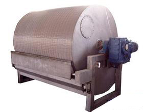
3.2 Product Structure Model XDL20 vacuum filter has compact structure and exquisite design. Made of high quality materials, it has a very strong mechanism. All parts are made of stainless steel, with exquisite processing and low maintenance cost. It mainly consists of transmission device, tank body, drum device, stirring device and scraper device.
3.2.1 transmission The spiral bevel gear reducer with shaft-mounted anti-rotation arm, which is developed according to the use characteristics of the filter, is selected as a partner from enterprises with advanced international structure and famous brand reducer production. The gear surface is ground after hardening treatment. This machine adopts frequency conversion speed-regulating motor, which can realize stepless speed change of speed reducer. The reducer has stable transmission and lower noise than the national standard.
3.2.2 tank body According to the size of the diameter of the vacuum rotating drum, 10%-15% of the rotating drum is immersed in the liquid surface of the tank body, and a filter screen flushing pipe is arranged at the edge of the tank body along the lower part of the scraper. It is used to flush the filter screen after the equipment completes a working cycle. The edge of the tank body is provided with a feed pipe under the stirring device, the feed pipe is a stainless steel pipe, and a slotted hole is formed on the side surface of the feed pipe. When in operation, the angle of the feed pipe and the feed pressure are adjusted so that the slurry flows into the tank body evenly along the tank body to ensure uniform distribution of the material over the entire length of the tank body. One side of the tank body is provided with a drain outlet and an overflow port, and the overflow port is provided with a movable baffle plate, so that the level of liquid in the tank body can be adjusted according to requirements. Apart from containing starch slurry, the tank body is also the support of the whole equipment, and the weight of all parts of the machine falls on the tank body. The supporting plate of the trough body is provided with anchor bolts which are connected with the equipment foundation.
3.2.3 drum unit This machine is a gridless rotary drum vacuum filter and does not partition in the circumferential direction of the whole rotary drum. A plurality of suction pipes are uniformly distributed in the drum, and filtrate directly flows into the discharge end after passing through the suction pipes. It is equipped with a distribution head, the vacuum system has small pressure loss and large filtration capacity per unit area. The filter surface on the drum surface adopts stainless steel mesh with special mechanism as the cushion layer. The whole drum has a welded structure, which is compact and light in weight.
3.2.4 stirring device The stirring device of the equipment uses compressed air as power, and the automatic reciprocating cylinder drives the stirrer to reciprocate at a speed of 10-15 times per minute through rocker arms, push rods and the like. The stirring device with the structure operates stably and does not cause the slurry entering the tank body to precipitate.
3.2.5 Scraper Device Both sides of the whole scraper device are supported by bearings, so the resistance is small and the swinging is stable. With compressed air as power, the scraper is driven to move by an automatic reciprocating cylinder, a push rod, a connecting rod and the like. When the cylinder is energized, the scraper deviates from the drum and approaches when the power is cut off. The distance between the scraper blade and the vacuum drum is adjusted by adjusting bolts in the bearing chamber. The scraper holder of the scraper device is made of stainless steel. A number of high-hardness alloy blades are fixed on the tool rest by screws, and the rear angle of the blades (the included angle between the blades and the tangent line of the rotating drum) is not less than 11 degrees, so as to ensure a sharp cutting edge when the scraper works and avoid wiping the micropores of the pre-hung layer to death.
4. Transportation and hoisting XDL20 vacuum filter, see attached figure 1 "filter structure diagram" (weight: 4000 kg) As the vacuum filter is only one part of the whole process, the following matters must be paid attention to during transportation:
4.1 The equipment is usually assembled before delivery and has undergone no-load and clean water test run. 4.2 In case of long-distance transportation, in order to avoid the mechanical deformation of the transmission shaft due to turbulence during transportation, which may affect the use effect, the machine body and reducer shall be transported separately. After the reducer is removed, in order to prevent the transmission shaft from being damaged by external force, the transmission shaft should be coated with anti-embroidery oil and wrapped with oil cloth. Pay attention to avoid collision between the transmission shaft and other objects and hanging other objects on the transmission shaft during transportation.
4.3 When hoisting the whole machine, the hook shall be hung in the four lug holes on both sides of the slot body, and a hoisting beam shall be attached between the two hoisting ropes to avoid damage caused by uneven stress.
4.4 If the drum needs to be hoisted, the hoisting rope must be hung at the shaft heads at both ends of the drum, and a hoisting crossbeam must be additionally installed between the two hoisting ropes.
5. Installation
5.1 Pour the equipment foundation with reinforced concrete according to the foundation drawing.
5.2 After the foundation is cured, if the foundation is transported as a whole, the tank body and the whole drum shall be hoisted and installed on the cement foundation. For split transportation, the tank body must be hoisted and installed on the cement foundation. Then, according to the alignment adjustment of the center line of the tank body, a ruler is placed on the rotating drum, and the levelness of the equipment is checked with a secondary precision level meter, with an allowable error of 0.10/1000. After leveling, pour concrete into the reserved holes of foundation bolts, and finally fix the foundation bolts.
5.3 Flexible connection must be adopted between the discharge pipe and the fixed pipeline, and support can be added when necessary.
5.4 The liquid level in the tank body can be controlled through the overflow port, and the feeding speed can also be adjusted. Try to avoid slurry backflow, so as to avoid slurry waste.
5.5 The rotating speed of the drum shall be selected according to the material properties, process conditions, production capacity and other factors.
5.6 According to the electrical schematic diagram, connect the motor, cylinder and electric control cabinet, and connect the cylinder with the air source. After connection, the seal of the motor junction box must be in good condition and reliable, the air pipe must be free of air leakage, and the motor junction box must operate normally.